PIN Diode Attenuators
- 18 to 110 GHz Product Range
- Full band versions up to 60 GHz
- Integrated Drivers
- Fast switching times
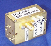
The HVA series of broadband PIN Diode attenuators covers the waveguide bands from 18 to 110 GHz. Full waveguide band coverage is available up to 60 GHz. The attenuators are available for applications requiring variations in power levels using a control voltage. A 0 to +5 V tuning range is used to control the attenuation level.
These designs utilize a low loss finline structure with silicon or GaAs beam lead diodes for minimum insertion loss and optimum attenuation flatness. Standard attenuation values range from 30 dB up to 50 GHz to 15 dB at 100 GHz. Options for alternateattenuation values can be offered with low loss versions and isolation levels up to 40 dB.
Specifications @ 35°C TCASE. Specifications subject to change w/o notice.
| Part Number | Frequency (GHz) | WG / Flange (WR# / UG#) | Maximum Bandwidth | Insertion Loss (dB) | Isolation (dB) |
|---|---|---|---|---|---|
| HVA4203 | 18.0 – 26.5 | 42 595/U | Full | 1.2 | 30 |
| HVA3403 | 22.0 – 33.0 | 34 595/U | Full | 1.6 | 30 |
| HVA2803 | 26.5 – 40.0 | 28 599/U | Full | 1.8 | 30 |
| HVA2203 | 33.0 – 50.0 | 22 599/U-M | Full | 2.0 | 30 |
| HVAM1201 | 71.0 – 86.0 | 12 387/U | 5GHz | 4.5 | 12 |
| HVAM1201 | 71.0 – 86.0 | 12 387/U | 5 GHz | 7.0 | 24 |
| General Specifications | |
|---|---|
| Bias | ± 15.00 VDC @ ± 20 ma |
| Control Voltage | 0 to + 5.00 V |
| VSWR Low Loss State | 2:1 typical |
| VSWR @ Full Attenuation State | 3.5: typical |
| Switching Speed (10 – 90% ) | 500 ns |
| Maximum RF Power | Spec compliant to 100 mW Operates to 500 mW without damage |
| Operating Temperature | 0 to +60°C |
Requesting quotes
When requesting a quote for HVA PIN Diode Attenuators, please specify required frequency range, isolation level and any other required specifications. HVA attenuators are built to order and will be optimized for the bandwidth specified by the customer. The part number guide be- low can also be used as a reference for requesting quotes.
Downloads (click to download)
PIN Diode Attenuator data sheet (includes listing of all available standard models)
HXI Company Overview
Follow Us