Broadband Detectors
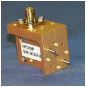
The HFD series broadband detectors cover full waveguide bands from 40 – 170 GHz . They utilize a low loss finline structure mated to a zero bias Schottky beam lead diode for maximum output and bandwidth. The RF energy is converted to a DC voltage resulting in a detector mount having high levels of sensitivity over a broad dynamic range. Since zero bias diodes are used, no bias is required and both negative and positive voltage outputs are available.
The HFD series detectors are used wherever DC conversion of RF signals is required such as with scalar measurement systems. Detectors can be optimized for specific frequency coverage and can be matched as pairs if required.
| Part Number | Frequency (GHz) | Waveguide | Standard Flange | Voltage (1) Sensitivity MV/mW (min) | Maximum Flatness (dB) |
|---|---|---|---|---|---|
| HFD22P | 33.0 – 50.0 | WR – 22 | UG-599/U-M | 1200 | ±2.0 |
| HFD19P | 40.0 – 60.0 | WR – 19 | UG-599/U-M | 1200 | ±2.0 |
| HFD15P | 50.0 – 75.0 | WR – 15 | UG-385/U | 1200 | ±2.0 |
| HFD12P | 60.0 – 90.0 | WR – 12 | UG-387/U | 1000 | ±2.5 |
| HFD10P | 75.0 – 110.0 | WR – 10 | UG-387/U-M | 600 to 95 GHz 300 above 95 GHz | ±2.5 |
| HFD08P | 90.0 – 140.0 | WR- 8 | UG-387/U-M | 300 @ 94 GHz 80 @ 140 GHz | |
| HFD07P | 110.0 – 170.0 | WR-7 (WR-6.5) | UG-387/U-M | 200 @ 110 GHz 80 @ 140 GHz |
Notes
- Measured @ -20 dBm into a video output load of 1 meg ohm
- Flange options available for WR-22 and WR-19. See next page for options.
General Specifications
Maximum Input Power: 100 mW
Operating Temperature: 0 to +60°
Video Output: SMA Female
VSWR: 3:1 typical
Part Number Guide
Downloads (click to download)
Broadband Detectors
75 – 110 GHz Planar Detector, HFD10P-H1
90 – 140 GHz Planar Detector, HFD08P-H1
110 – 170 GHz Planar Detector, HFD06P-H1
HXI Company Overview
Follow Us